Showing posts with label shop tips. Show all posts

Wednesday, September 27, 2023

Single Speed Questions - Part 2

 If you missed yesterday's post, click the link below to read that.

Single Speed Questions - Part 1

Today's post will continue on with some more gear/hardware/technique related questions about single speed use, and tomorrow we'll get into some more gear ratio stuff. 

So, buckle up and grab a cuppa. Here we go!

The first question we will look at today regards set-up of a single speed chain. 

How and why would you adjust the sliding dropouts, (or eccentric bottom bracket, track ends, or swinging drop outs) and where are they supposed to be adjusted to?

This answer could get really into the weeds with trying to describe each adjustable feature of any particular single speed frame. So, I am going to assume that you will have researched the "how you adjust" your particular drop out or eccentric bottom bracket. I will focus on how to know when your chain is adjusted properly instead. This seems to me to be the thing that trips up people the most, not how their adjustments work. In other words, it's all about chain tension and how you determine what is "right". 

First, you'll need to figure out how long your chain needs to be. A chain tool to help aid you making the correct adjustment is all you'll need here for tools. I recommend getting something like THIS or THIS. These chain tools will allow you to loosen a stiff link. (See THIS video to learn how to do this)
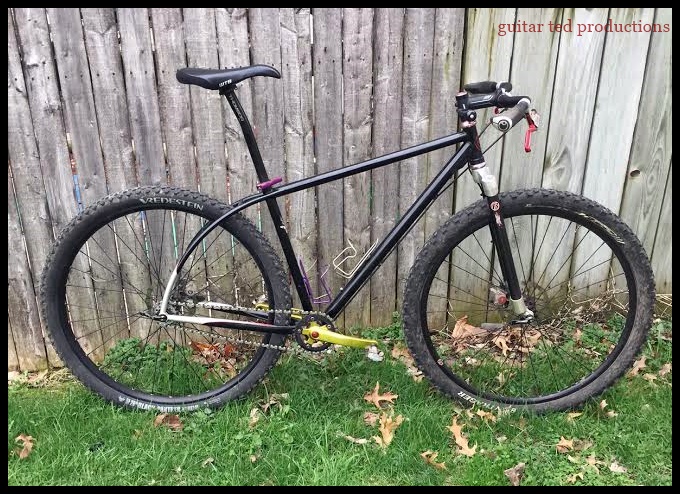
To determine chain length and to allow for a bit of adjustability, move your rear wheel, (or eccentric bottom bracket) so that it sits in about the mid-point of adjustability. You could move the wheel forward a bit or backward a bit from this point. (Or the bottom bracket if eccentric) Okay, now lace your chain, (I recommend a SRAM PC830 for most single speed applications), and you should find that you have far too much chain. Bring the chain together, overlapping the ends, until you see about where the ends would have to be to meet to make things work out on the bike. 

You may not be able to make a perfect fit where your wheel is at, but remember, you can go and adjust for that. Keep in mind the a pair of inner plates has to mate with a pair of outer plates. (I typically stay away from quick links on a single speed, by the way.) Note how much of the chain will have to be removed. Err on the side of "too long", if you are not sure. Then using your chain tool, push out a link's pin, but juuuust enough that it doesn't go all the way through the last outer plate. (See images below) You want to be able to push that pin back through here in a bit. Okay, now with your predetermined amount of chain removed, double check the length. Hopefully you are right in the ball park, but if not you can shorten it up a link or two here. Make sure you end up with one exposed inner set of plates, and one outer set at the other end of the chain. Not two sets of outers, or vice versa! 

Then join the two ends as they should mate together. If your pin sticking out of the outer plate is protruding slightly on the inside of that plate, this may help you hold the chain in place a bit as you reconnect the loose ends. (Again, please refer to the images below for reference)

Once you've determined an approximate chain length, push out the pin which will cut the chain at the spot you've chosen
Don't push that pin all the way out. You want it to look like this when you are done. Clean up any extraneous flashing and bits of metal.

The opposite, inner pair of plates at the other end of the chain now can be "snapped" into place. It may take a little effort to do this. Also- Make sure the chain is laced through the frame when doing this!

Now carefully drive that pin back into the chain. You will feel more resistance when the pin starts to go through the outer plate. See next image.....

Ideally, you want to push that pin juuuust a bit too far. See orange arrow.

Note the position of the chain in the chain tool. Now gently push that pin that sticks out a hair and this will free up the stiff link you created when putting the chain together.

Now you've hopefully come pretty close to the ideal chain length, but things are a bit slack, right? This is where you adjust the chain with whatever system you have on your bike. But how tight should you make the chain? There is a trick to doing this. 

Not all things that look "round" are actually "round". What I mean by this is that chain rings and cogs often are not perfectly round. They will usually be, but not in every instance, somewhat elliptical in shape, although we cannot see that with the naked eye.

Checking for chain deflection to help adjust chain tension.

  If you adjust your tensioning system to where the chain has a bit of tension on it, stop there and then rotate the crank about a quarter of a turn. Now, finding a spot in the chain midway between each gear, use your finger and deflect the chain downward. If you cannot push it down a half inch, the chain is too tight. Loosen your adjustment until you get that amount of deflection, but now rotate the crank a 1/4 turn again and check. Maybe now you are seeing 3/4's of an inch deflection. Okay...,.go another 1/4 turn. If you get back to 1/2 inch, you are good. But let's say that you see an inch of deflection at that point after the first adjustment. Go back on your adjustment and then continue. Essentially, what you want to do is to adjust for that 1/2 inch of deflection wherever the chain is "tightest" during the crank's rotation. 

A chain that is too tight will potentially cause accelerated wear, be resistant to rotation, robbing you of power, and is more susceptible to breaking under stress. Too loose and the chain is apt to jump off the cogs at an inopportune time, which may cause a serious crash and injury. 

Here you can see various spacers used to align the rear cog with the chain ring on a geared free hub body.

Chain Line is VERY important with a single speed set up. Chain line is the "line" a chain makes from the front chain ring to the rear cog. If this "line" deflects inward or outward from the chain ring as it goes to the rear cog, you have a BIG problem! Ideally you want this set of components to all be in the same plane. No chain deflection at all. If you are using a geared rear wheel to mount a single speed cog on, you'll need to set up spacers to align the cog with the front chain ring to achieve a straight chain line. 

If your chain line is off, meaning that the front chain ring and rear cog are not on the same plane, you will get noises, popping, and you may even have the chain jump off the rear cog. this can result in a serious accident and injury. So, pay attention to chain line! 

A single speed specific hub is generally set to a certain chain line, and at that point you'd need to adjust your chain ring. You might be able to do that by mounting the chain ring on either the front of the chain ring mounting tabs or behind them. You may be stuck in that regard depending upon the type of crankset you chose. You may also be able to do some adjusting with the bottom bracket using spacers and shims. See your local bike shop if this gets to be an issue with your single speed set up.

That'll do it for today. Tomorrow we will talk about crank length and how that can affect your single speed success or failure. I will also touch upon gearing and how to choose a good place to start out.

Wednesday, March 15, 2023

The "Boucher Route" Cabling Method Explained

My cabling routing I use which was learned from Jason Boucher
Earlier this week I received a comment from a reader asking if I might explain what the "Boucher Route" was which I used on my new Singular Cycles Mk3 Gryphon build. This post will help explain not only what that routing is, but the name behind it, and why I use that name for this technique. 

History: When I went to visit Quality Bicycle Products in late 2008 to see and ride the then new Salsa Cycles Fargo, I was invited to tag along with Jason Boucher, who was then the brand manager for Salsa Cycles. 

As we prepared the bikes at Jason's home for the Fargo ride the following day, Jason taught me a new-to-me cabling method for external routing of a geared drop bar bike that was elegant and kept the head tube from being rubbed by cable housing. I found the idea so worth using that I associated it with Jason Boucher and ever since I have called this method of cabling a drop bar bike "The Boucher Route". 

Now, Jason would be the first to tell you that this is not his idea or invention, and that is true. However; this is what I am calling it, and have been calling it for over ten years, so there! Ha! It is what it is....

Besides, I wanted to honor Jason for his friendship and early advocacy of my efforts in reviewing product and events production. These days Jason has moved on from the bicycle business to doing his own line of camera bags. Check those out HERE

My old "Fat Fargo" from 2015 using the "Boucher Route" cabling method.

 Explainer: Okay, so let's dig into what is going on here. I've done the "Boucher Route" on nearly every geared, disc brake drop bar bike I have owned since 2008, but this "Fat Fargo" example from 2015 is a great example since I employed two different shifters on the same bike. Note: this routing only works in its entirety for disc brake drop bar bikes. Cantilever brake bikes will require different front brake cable routing than this example does.

#1: This is the route for the rear shifting which you would use with an external cable housing run for most earlier Shimano STI levers up to about 2010-ish when Shimano started routing the cables under the bar tape. Note that instead of having the right side cable go to the right side cable stop, it goes to the left. The example here is showing a Gevenalle shifter set up.

#2: Here you see the route for the left shifter, which in this case is a bar-end shifter, but the routing would exit the bar tape in a similar manner for STI/SRAM under-the-bar-tape shifting as well. The left side shifter cable housing goes to the right side of the bike.

#3: The brakes. Note that the brake cable route for the left/front goes behind the head tube and fork from the right. So, you do not go from the left brake and try to make a tight curve down toward the left fork leg here, On steel frames you have the option of cable tying the housing to the center hole on the fork crown, but you do not have to do this in every case. The rear/right side brake cable housing goes to the down tube cable mounts from the left side of the head tube

Benefits: The "Boucher Route" keeps the gentle curves which cause less cable friction and also it keeps the cable housings bowed outwards from the head tube in a better way. This causes less paint damage due to its keeping the housings from contacting the paint on the head tube unless you turn the bars enough that the cable housings eventually contact the frame at the head tube.  

Cons: The "Boucher Route" can cause really long runs of cable for the derailleurs and rear brake. I've had to use tandem cables many times, longer housings, and those are more expensive, Also- It won't work on every bike. Typically I have found this is a great idea for steel and titanium bikes. However, many carbon bikes and lots of aluminum bikes won't benefit from this, or they have internal cable routing, or no cables because you have hoses and wireless shifting.

I hope that explains the "Boucher Route", its history, and how it might be a benefit to you. Got any more questions? You know what to do! 

Thanks for reading Guitar Ted Productions!

The "Boucher Route" Cabling Method Explained

My cabling routing I use which was learned from Jason Boucher
Earlier this week I received a comment from a reader asking if I might explain what the "Boucher Route" was which I used on my new Singular Cycles Mk3 Gryphon build. This post will help explain not only what that routing is, but the name behind it, and why I use that name for this technique. 

History: When I went to visit Quality Bicycle Products in late 2008 to see and ride the then new Salsa Cycles Fargo, I was invited to tag along with Jason Boucher, who was then the brand manager for Salsa Cycles. 

As we prepared the bikes at Jason's home for the Fargo ride the following day, Jason taught me a new-to-me cabling method for external routing of a geared drop bar bike that was elegant and kept the head tube from being rubbed by cable housing. I found the idea so worth using that I associated it with Jason Boucher and ever since I have called this method of cabling a drop bar bike "The Boucher Route". 

Now, Jason would be the first to tell you that this is not his idea or invention, and that is true. However; this is what I am calling it, and have been calling it for over ten years, so there! Ha! It is what it is....

Besides, I wanted to honor Jason for his friendship and early advocacy of my efforts in reviewing product and events production. These days Jason has moved on from the bicycle business to doing his own line of camera bags. Check those out HERE

My old "Fat Fargo" from 2015 using the "Boucher Route" cabling method.

 Explainer: Okay, so let's dig into what is going on here. I've done the "Boucher Route" on nearly every geared, disc brake drop bar bike I have owned since 2008, but this "Fat Fargo" example from 2015 is a great example since I employed two different shifters on the same bike. Note: this routing only works in its entirety for disc brake drop bar bikes. Cantilever brake bikes will require different front brake cable routing than this example does.

#1: This is the route for the rear shifting which you would use with an external cable housing run for most earlier Shimano STI levers up to about 2010-ish when Shimano started routing the cables under the bar tape. Note that instead of having the right side cable go to the right side cable stop, it goes to the left. The example here is showing a Gevenalle shifter set up.

#2: Here you see the route for the left shifter, which in this case is a bar-end shifter, but the routing would exit the bar tape in a similar manner for STI/SRAM under-the-bar-tape shifting as well. The left side shifter cable housing goes to the right side of the bike.

#3: The brakes. Note that the brake cable route for the left/front goes behind the head tube and fork from the right. So, you do not go from the left brake and try to make a tight curve down toward the left fork leg here, On steel frames you have the option of cable tying the housing to the center hole on the fork crown, but you do not have to do this in every case. The rear/right side brake cable housing goes to the down tube cable mounts from the left side of the head tube

Benefits: The "Boucher Route" keeps the gentle curves which cause less cable friction and also it keeps the cable housings bowed outwards from the head tube in a better way. This causes less paint damage due to its keeping the housings from contacting the paint on the head tube unless you turn the bars enough that the cable housings eventually contact the frame at the head tube.  

Cons: The "Boucher Route" can cause really long runs of cable for the derailleurs and rear brake. I've had to use tandem cables many times, longer housings, and those are more expensive, Also- It won't work on every bike. Typically I have found this is a great idea for steel and titanium bikes. However, many carbon bikes and lots of aluminum bikes won't benefit from this, or they have internal cable routing, or no cables because you have hoses and wireless shifting.

I hope that explains the "Boucher Route", its history, and how it might be a benefit to you. Got any more questions? You know what to do! 

Thanks for reading Guitar Ted Productions!

Wednesday, February 22, 2023

Tool Inspection Time

Don't neglect the inspection of your tools!
 It struck me the other day as I reached for a 4mm hex key that maybe as cyclists there are some of you that don't pay a lot of attention to your tools. This can get you in big trouble down the road, especially if you have been using the same tools for many years. You know, that trusty multi-tool? Maybe it is a set of hex keys you often use at the home shop. Whatever the case may be, tools need looking after, and a well-worn tool, while a beautiful thing, is a time bomb waiting to blow up some project or repair. 

And you all know that never happens at a convenient time! 

So, I thought since I have seen tools wear out and since I have seen what to look for in terms of wear and what that can do if you do not address that, I would drop a few tips in the blog today. This might be handy now as well since "gravel" season - well, really cycling season overall - is about to kick off for the year in the Northern Hemisphere. 

I'll drop hints according to tool type and try to include a few images to help illustrate my points. 

Hex (Allen) Keys: These tools are perhaps the most used of all the tools a cyclist might have besides an air pump. (Note: These tips can mostly be used for the inspection of Torx keys also) The typical high-use keys are the 4mm, 5mm, and 6mm keys with a nod to the bastard child 2.5mm key. (Thanks SRAM!) Hex keys, (also known as Allen wrenches), can become very worn after several years of use. Using a worn hex key is a recipe for a rounded out fastener. You can inspect the ends of your hex keys and maybe see wear in the form of deformation of the hexagonal shape. You may see rounded off corners as well. Anything but sharp, crisp corners should alert you to a potential problem. 

Note the deformation of the 4mm end on the left  here.

Ball end, or Bondhus type hex key ends are even worse for this issue. Pay particular attention to these as they can lose there shape rather easily without your noticing. Tip: NEVER use a ball-end hex key to do any heavy torque work either loosening or tightening. That's not going to go well in the long run. 

Sometimes you can cut off the damaged end and save the tool, but be aware that high-speed cut-off discs or grinders can take the temper out of the metal due to heat and make the tool worse than it was when you started. I recommend a hand-held hack saw if you want to attempt this. Make sure you lightly debur the edges with a file if you should decide to try to extend the life of a hex key. 

A Quick Note On Hack Saws: As long as I'm writing about hack saws- Keep in mind a hack saw only cuts in one direction only (away from you) and that you should always use the entire blade! Most people apply way too much downward pressure (wrong- let the blade do the work), and saw back and forth in the middle of the blade, quickly wearing out that short section of the blade while either end goes unused. As an old jeweler once told me- "You pay for the whole blade. Use all of it then!"

A good chain breaker pin should look like this.
Chain Breaker: These are great tools in the case where you break a chain, but if you have used your chain breaker several times, you may want to look at the pin that pushes out the rivets which hold the side plates together. That pin goes under a lot of stress and pressure with each usage. That can cause the pin to deform, or more likely than that, bend. A bent or deformed pin usually can be replaced, (on good quality tools) so make sure that you replace your chain pin now before you find out that it is bent or mushroomed out when you are trying to use it on some rural road. 

Torque Tools: These handy gizmos are very popular these days for torquing down hex bolts on stem face plates, stem attachments to steer tubes, and other torque sensitive fasteners. However, their bits can also fall prey to the same issues that all hex keys do after a lot of usage. If those bits are replaceable, and they are deformed or very worn, you should replace them. If they are not? New tool time. 

Torque keys can wear out and fall out of spec. Beware!

Also, those torque settings should always be periodically checked against a known, certified torque wrench from time to time. Any torque key that is out of spec should be replaced and not used again. Remember: Tools are not going to last forever! Especially if you use them a lot. Don't want to have to spend the money? Then don't use the tool. But your alternative is what? Seeing a professional mechanic should be the answer there. Let that person foot the bills for tools and the knowledge to use them. But pay that person accordingly with a cheerful heart. 

Otherwise the maintenance and liability for not doing that maintenance is on you. 

Cleaning: This is also the time of the year to inventory and clean up any rucksacks, hydration packs, top tube bags, or any frame bag and see what is in there. It isn't uncommon for riders to find multi-tools, old tubes, food wrappers, or even money that they had forgotten about in the depths of some bag. More importantly, cleaning up the bag and tools that may be in it make life a lot smoother for the upcoming season of riding. Plus, you'll have a handle on what you might need to add or subtract from those bags! 

Those are just a few tips I can think of for the tools you most likely use for your bicycles. Got any other ideas? Let me know. If there are more than a few different suggestions, I'll make a "part 2" for this post.

Tool Inspection Time

Don't neglect the inspection of your tools!
 It struck me the other day as I reached for a 4mm hex key that maybe as cyclists there are some of you that don't pay a lot of attention to your tools. This can get you in big trouble down the road, especially if you have been using the same tools for many years. You know, that trusty multi-tool? Maybe it is a set of hex keys you often use at the home shop. Whatever the case may be, tools need looking after, and a well-worn tool, while a beautiful thing, is a time bomb waiting to blow up some project or repair. 

And you all know that never happens at a convenient time! 

So, I thought since I have seen tools wear out and since I have seen what to look for in terms of wear and what that can do if you do not address that, I would drop a few tips in the blog today. This might be handy now as well since "gravel" season - well, really cycling season overall - is about to kick off for the year in the Northern Hemisphere. 

I'll drop hints according to tool type and try to include a few images to help illustrate my points. 

Hex (Allen) Keys: These tools are perhaps the most used of all the tools a cyclist might have besides an air pump. (Note: These tips can mostly be used for the inspection of Torx keys also) The typical high-use keys are the 4mm, 5mm, and 6mm keys with a nod to the bastard child 2.5mm key. (Thanks SRAM!) Hex keys, (also known as Allen wrenches), can become very worn after several years of use. Using a worn hex key is a recipe for a rounded out fastener. You can inspect the ends of your hex keys and maybe see wear in the form of deformation of the hexagonal shape. You may see rounded off corners as well. Anything but sharp, crisp corners should alert you to a potential problem. 

Note the deformation of the 4mm end on the left  here.

Ball end, or Bondhus type hex key ends are even worse for this issue. Pay particular attention to these as they can lose there shape rather easily without your noticing. Tip: NEVER use a ball-end hex key to do any heavy torque work either loosening or tightening. That's not going to go well in the long run. 

Sometimes you can cut off the damaged end and save the tool, but be aware that high-speed cut-off discs or grinders can take the temper out of the metal due to heat and make the tool worse than it was when you started. I recommend a hand-held hack saw if you want to attempt this. Make sure you lightly debur the edges with a file if you should decide to try to extend the life of a hex key. 

A Quick Note On Hack Saws: As long as I'm writing about hack saws- Keep in mind a hack saw only cuts in one direction only (away from you) and that you should always use the entire blade! Most people apply way too much downward pressure (wrong- let the blade do the work), and saw back and forth in the middle of the blade, quickly wearing out that short section of the blade while either end goes unused. As an old jeweler once told me- "You pay for the whole blade. Use all of it then!"

A good chain breaker pin should look like this.
Chain Breaker: These are great tools in the case where you break a chain, but if you have used your chain breaker several times, you may want to look at the pin that pushes out the rivets which hold the side plates together. That pin goes under a lot of stress and pressure with each usage. That can cause the pin to deform, or more likely than that, bend. A bent or deformed pin usually can be replaced, (on good quality tools) so make sure that you replace your chain pin now before you find out that it is bent or mushroomed out when you are trying to use it on some rural road. 

Torque Tools: These handy gizmos are very popular these days for torquing down hex bolts on stem face plates, stem attachments to steer tubes, and other torque sensitive fasteners. However, their bits can also fall prey to the same issues that all hex keys do after a lot of usage. If those bits are replaceable, and they are deformed or very worn, you should replace them. If they are not? New tool time. 

Torque keys can wear out and fall out of spec. Beware!

Also, those torque settings should always be periodically checked against a known, certified torque wrench from time to time. Any torque key that is out of spec should be replaced and not used again. Remember: Tools are not going to last forever! Especially if you use them a lot. Don't want to have to spend the money? Then don't use the tool. But your alternative is what? Seeing a professional mechanic should be the answer there. Let that person foot the bills for tools and the knowledge to use them. But pay that person accordingly with a cheerful heart. 

Otherwise the maintenance and liability for not doing that maintenance is on you. 

Cleaning: This is also the time of the year to inventory and clean up any rucksacks, hydration packs, top tube bags, or any frame bag and see what is in there. It isn't uncommon for riders to find multi-tools, old tubes, food wrappers, or even money that they had forgotten about in the depths of some bag. More importantly, cleaning up the bag and tools that may be in it make life a lot smoother for the upcoming season of riding. Plus, you'll have a handle on what you might need to add or subtract from those bags! 

Those are just a few tips I can think of for the tools you most likely use for your bicycles. Got any other ideas? Let me know. If there are more than a few different suggestions, I'll make a "part 2" for this post.

Thursday, October 20, 2022

Guitar Ted's How-To: Rear Derailleur set-Up Basics - Part 2

Welcome to Part 2 of how to set up a rear derailleur from scratch on your bike. Again, this applies to the way I would take a new rear derailleur for a mechanical system and set it up to work properly. This would also work for anyone swapping on a used rear derailleur as well. While this doesn't cover electronic rear derailleurs, many of the same basics still apply. 

Now, if you missed the basics of rear derailleurs, that post is HERE and a link to yesterday's post is HERE. I will assume you have read and understood that previous material. 

Keep in mind that if you have any hesitation at all in doing this task, stop and seek the help of a professional bicycle mechanic. Getting any of this wrong can lead to serious injury, property damage, and even death. So, unless you are confident in your mechanical skills and unless you own the proper tools, don't attempt this! 

Okay, with that out of the way, I will remind you that this post only will deal with how to set up the lower limit screw.  How to set up the "B Tension" screw is best done while doing a tune on the cable and rear shifting, so that will come later. . See that link for the earlier steps in this process which MUST be completed BEFORE you do these steps. Now, on with the show.....

The "LOW LIMIT" screw does not come into play until the rear derailleur is at full extension. This happens in your lowest gear on the cassette, or the "biggest cog" if you think of things in that manner. Its job is to prevent the rear derailleur's travel inboard to the point that the chain goes over the top of that last cog and into the spokes. It also aligns that upper jockey wheel on the rear derailleur so it is perfectly in-line with the last cog of the cassette. 

Above you can see #1 which is the "LOW" screw and where it hits the inner portion of the parallelogram of this Shimano XT rear derailleur at point #2. Remember from yesterday's post that turning that "LOW" screw clockwise prevents travel inboard and turning it counter-clockwise allows that travel to continue further inboard toward the spokes. This assumes that your cable tension is correct, that you have the correct, operational shifter, and nothing is damaged or bent on a complete system. But for this job, we aren't worried about that just yet. 

Now, for a quick diversion...... Since setting the "LOW" limit screw is best done with a chain on, I am going to show you a couple of hacks I use to make chain installation a bit easier. Both of these work best if you have a repair stand, by the way. 

First, you want to get the derailleur in the position I have shown to the left here. This will probably mean that your bike will have its front wheel on the ground and the back one straight, or almost so, above it in the work stand. What you want is to make a straight path downward for the chain toward the ground through the derailleur cage. 

This allows you to use gravity to your advantage, instead of fighting gravity - if you were trying to put the chain through the rear derailleur with the bike in a horizontal position. This technique I am sharing makes the job of threading a chain through a derailleur far easier. But again- it works best with a repair stand. Don't have one? Well, I would guess that if you have read this far, you want to do some of your own work on your bicycles. The best thing you can add to your tool stash is a repair stand. Get one!

Drop the chain in from the top, using gravity to feed it through the cage.

Okay, now on with the show... Tip: Make certain that you have cut your chain to length (use the old one as a guide if you can), and make sure you thread the chain in the right orientation. 10, 11, and 12 speed chains will likely have either a top side or bottom, or a right and left orientaion. Check your chain manufacturer's tech spec guide or ask a mechanic if you are not sure about this. Most 9 speed, 8 speed, and 7 speed chains are not affected by this.

Using gravity, you should be able to drop the chain in from the top, through the cage, and past the upper jockey wheel of the derailleur, (which is the lower one as this is oriented here in the image) , and then pass through at least half the chain. You can even thread the chain through a front derailleur at this time, if that applies to your bike. Then adjust your stand back so the bike sits horizontally again. 

Hack #2: Use a bungee cord to hold the cage forward like this to relieve chain tension for ease of quick link attachment.

Ever had trouble connecting those Shimano quick links? Read on...

Now for Hack #3- This applies mostly to Shimano quick links, but some SRAM 7 & 8 speed links are stubborn to go into place as well. If you have had trouble connecting a quick link like this, here's a quick way to solve the problem. First, carefully attach the link with the chain tension relieved as I have shown with the bungee. Try to get the link as tight as you can first, as I have shown immediately above with this Shimano 11 speed link. 

Then, carefully, slowly pedal the bike forward so the quick link is in the "top run" of the chain as I have shown immediately above here. Get the quick link about midway from the cassette cog and the chain wheel. Then, grab a rubber mallet, (you can use your hand, but it usually hurts if you do!), and apply the rear brake firmly with one hand and then strike a pedal (Usually should be the right side since it is closet to you)  sharply with the rubber mallet, as if you were going to pedal forward. This will snap the link into place. Done! 

Now- On to setting initial "LOW" limit for the derailleur. You'll see why I like to have the chain on for this in a minute.... (Here is a link to yesterday's post for reference if needed)


With the rear derailleur on the smallest cog on the cassette, place your hand as I have shown here on the rear derailleur. Use your left hand, as you'll need your right hand to pedal with. Pedaling slooooowly, push with your thumb on the derailleur's knuckle in the direction shown. (Towards the inboard side of the bike). 

The derailleur should start walking the chain up the cassette toward the biggest cog. You may find that with a new rear derailleur that you can only get so far, then you cannot push the derailleur any further, but you are two, maybe three cogs from the largest cassette cog. Okay, if that is the case, you need to turn the "LOW" limit screw counter-clockwise. Always make small, incremental adjustments. I'd turn it maybe a quarter turn at a time, and recheck how far the derailleur can be pushed up. Repeat the process until you can get the chain to drop into the last gear on the cassette, but no further!

Now, lets say that you can push that chain up and it wants to go over the last cog if you keep pushing. (This is why you want to pedal SLOWLY and be very careful) If that seems to be the case, the "LOW" limit screw needs to be turned clockwise, again a quarter turn at a time, until you cannot push the chain off the last cassette cog. 

Showing the technique at the extreme end of the derailleur's travel here.

Keep in mind that you do not need to use excessive force, or much force at all to manage this technique. The carefully applied force and slow movement of the drive train as you pedal will yield the best results here. 

Now if you've found that point where you can get the chain to drop in the last, largest cog on the cassette and not have the chain go over it, you've got the "LOW" limit in the ballpark. You should be okay as far as a safe system now. I'd recommend doing a finer adjustment if necessary when you get to adjusting the cable for shifting, but that will be for my next post in this series. I'll also show how to set up the "B" tension screw for optimal shifting when I get to how to tune the rear derailleur as well.

At this point, your basic set-up of the rear derailleur is complete. Stay tuned for more "How-To" posts soon.

Guitar Ted's How-To: Rear Derailleur set-Up Basics - Part 2

Welcome to Part 2 of how to set up a rear derailleur from scratch on your bike. Again, this applies to the way I would take a new rear derailleur for a mechanical system and set it up to work properly. This would also work for anyone swapping on a used rear derailleur as well. While this doesn't cover electronic rear derailleurs, many of the same basics still apply. 

Now, if you missed the basics of rear derailleurs, that post is HERE and a link to yesterday's post is HERE. I will assume you have read and understood that previous material. 

Keep in mind that if you have any hesitation at all in doing this task, stop and seek the help of a professional bicycle mechanic. Getting any of this wrong can lead to serious injury, property damage, and even death. So, unless you are confident in your mechanical skills and unless you own the proper tools, don't attempt this! 

Okay, with that out of the way, I will remind you that this post only will deal with how to set up the lower limit screw.  How to set up the "B Tension" screw is best done while doing a tune on the cable and rear shifting, so that will come later. . See that link for the earlier steps in this process which MUST be completed BEFORE you do these steps. Now, on with the show.....

The "LOW LIMIT" screw does not come into play until the rear derailleur is at full extension. This happens in your lowest gear on the cassette, or the "biggest cog" if you think of things in that manner. Its job is to prevent the rear derailleur's travel inboard to the point that the chain goes over the top of that last cog and into the spokes. It also aligns that upper jockey wheel on the rear derailleur so it is perfectly in-line with the last cog of the cassette. 

Above you can see #1 which is the "LOW" screw and where it hits the inner portion of the parallelogram of this Shimano XT rear derailleur at point #2. Remember from yesterday's post that turning that "LOW" screw clockwise prevents travel inboard and turning it counter-clockwise allows that travel to continue further inboard toward the spokes. This assumes that your cable tension is correct, that you have the correct, operational shifter, and nothing is damaged or bent on a complete system. But for this job, we aren't worried about that just yet. 

Now, for a quick diversion...... Since setting the "LOW" limit screw is best done with a chain on, I am going to show you a couple of hacks I use to make chain installation a bit easier. Both of these work best if you have a repair stand, by the way. 

First, you want to get the derailleur in the position I have shown to the left here. This will probably mean that your bike will have its front wheel on the ground and the back one straight, or almost so, above it in the work stand. What you want is to make a straight path downward for the chain toward the ground through the derailleur cage. 

This allows you to use gravity to your advantage, instead of fighting gravity - if you were trying to put the chain through the rear derailleur with the bike in a horizontal position. This technique I am sharing makes the job of threading a chain through a derailleur far easier. But again- it works best with a repair stand. Don't have one? Well, I would guess that if you have read this far, you want to do some of your own work on your bicycles. The best thing you can add to your tool stash is a repair stand. Get one!

Drop the chain in from the top, using gravity to feed it through the cage.

Okay, now on with the show... Tip: Make certain that you have cut your chain to length (use the old one as a guide if you can), and make sure you thread the chain in the right orientation. 10, 11, and 12 speed chains will likely have either a top side or bottom, or a right and left orientaion. Check your chain manufacturer's tech spec guide or ask a mechanic if you are not sure about this. Most 9 speed, 8 speed, and 7 speed chains are not affected by this.

Using gravity, you should be able to drop the chain in from the top, through the cage, and past the upper jockey wheel of the derailleur, (which is the lower one as this is oriented here in the image) , and then pass through at least half the chain. You can even thread the chain through a front derailleur at this time, if that applies to your bike. Then adjust your stand back so the bike sits horizontally again. 

Hack #2: Use a bungee cord to hold the cage forward like this to relieve chain tension for ease of quick link attachment.

Ever had trouble connecting those Shimano quick links? Read on...

Now for Hack #3- This applies mostly to Shimano quick links, but some SRAM 7 & 8 speed links are stubborn to go into place as well. If you have had trouble connecting a quick link like this, here's a quick way to solve the problem. First, carefully attach the link with the chain tension relieved as I have shown with the bungee. Try to get the link as tight as you can first, as I have shown immediately above with this Shimano 11 speed link. 

Then, carefully, slowly pedal the bike forward so the quick link is in the "top run" of the chain as I have shown immediately above here. Get the quick link about midway from the cassette cog and the chain wheel. Then, grab a rubber mallet, (you can use your hand, but it usually hurts if you do!), and apply the rear brake firmly with one hand and then strike a pedal (Usually should be the right side since it is closet to you)  sharply with the rubber mallet, as if you were going to pedal forward. This will snap the link into place. Done! 

Now- On to setting initial "LOW" limit for the derailleur. You'll see why I like to have the chain on for this in a minute.... (Here is a link to yesterday's post for reference if needed)


With the rear derailleur on the smallest cog on the cassette, place your hand as I have shown here on the rear derailleur. Use your left hand, as you'll need your right hand to pedal with. Pedaling slooooowly, push with your thumb on the derailleur's knuckle in the direction shown. (Towards the inboard side of the bike). 

The derailleur should start walking the chain up the cassette toward the biggest cog. You may find that with a new rear derailleur that you can only get so far, then you cannot push the derailleur any further, but you are two, maybe three cogs from the largest cassette cog. Okay, if that is the case, you need to turn the "LOW" limit screw counter-clockwise. Always make small, incremental adjustments. I'd turn it maybe a quarter turn at a time, and recheck how far the derailleur can be pushed up. Repeat the process until you can get the chain to drop into the last gear on the cassette, but no further!

Now, lets say that you can push that chain up and it wants to go over the last cog if you keep pushing. (This is why you want to pedal SLOWLY and be very careful) If that seems to be the case, the "LOW" limit screw needs to be turned clockwise, again a quarter turn at a time, until you cannot push the chain off the last cassette cog. 

Showing the technique at the extreme end of the derailleur's travel here.

Keep in mind that you do not need to use excessive force, or much force at all to manage this technique. The carefully applied force and slow movement of the drive train as you pedal will yield the best results here. 

Now if you've found that point where you can get the chain to drop in the last, largest cog on the cassette and not have the chain go over it, you've got the "LOW" limit in the ballpark. You should be okay as far as a safe system now. I'd recommend doing a finer adjustment if necessary when you get to adjusting the cable for shifting, but that will be for my next post in this series. I'll also show how to set up the "B" tension screw for optimal shifting when I get to how to tune the rear derailleur as well.

At this point, your basic set-up of the rear derailleur is complete. Stay tuned for more "How-To" posts soon.

Wednesday, October 19, 2022

Guitar Ted's How-To: Rear Derailleur Set-Up Basics - Part 1

 Hey Everyone! This is a follow-up on the series on "How-To" posts and this time I am continuing on with rear derailleurs. The basics on parts of a rear derailleur were discussed in THIS POST. Make sure you are familiar with the parts of a derailleur first as these following posts today and tomorrow will cover basic set-up and adjustments. Following these posts I will get into how to adjust shifting with the cable adjustment feature found on many rear derailleurs- but not all. Stay tuned for more on that coming soon. 

Today's post will get into how one would start to set up a brand new, or new-to-the-bike, rear derailleur. There are certain things you will want to do in a certain order that will make your life a lot easier when replacing one of these mechanisms. Also- while I will not discuss electronic rear derailleurs here, many of these basic principals still apply. Always refer to manufacturer's instructions, or take it to a bicycle technician if in doubt. Getting today's lesson wrong (or tomorrow's) can result in damaged parts and possibly a crash and injury/death. (No kidding!) So, if you have any questions at all about your understanding of these basics, get help! It's not worth it to take a chance here. 

Okay, with that out of the way, I would start this process with the chain off. You should have the rear wheel installed with whatever cassette you are going to use. The rear derailleur can then be mounted to the hangar of the frame (replaceable hangar in most cases, probably) and then we can get started.

First, let's familiarize ourselves with the important parts of today's discussion in regard to setting up a rear derailleur. I'll refer to the image above: Working from Left to Right...

  1. The cable fixing bolt, where the cable attaches. To get here, you may have to follow a circuitous path (SRAM) or specific leverage arms may have to be engaged. These are specific to individual derailleurs and may not apply in your case as well. Check manufacturer's manuals on your specific derailleur or consult an expert if in doubt. (This part won't be covered today or tomorrow)
  2. The "HIGH" limit screw on a Shimano rear mech is almost always the upper of two screws, or as in this case with a GRX rear derailleur, a pair of 2mm hex head bolts. These are used ONLY ONCE and then you should not have to touch them again. 
  3. The "LOW" limit screw. Both the "HIGH" and the "LOW" limit screws do what they say- They LIMIT derailleur travel. One on the "high"- or smallest cog of the cassette side, and the "low" is for the lowest gear/largest cassette cog side. These LIMIT the travel of the rear derailleur so your chain does not go off into the spokes or off on the other end into the frame. NOTE- These screws DO NOT AFFECT HOW YOUR BICYCLE SHIFTS, other than in one important way, which I will get to in my follow-up post. 
  4. The "B Tension" screw, or as in this case, a 2mm hex head screw. This is the adjustment for the upper jockey wheel's relationship to the cassette. This will be discussed in more detail when I get to the end of this post.

Now, if you have the rear derailleur mounted, with no chain on, and no cable attached, you are ready to set the derailleur's travel limits using the limit screws. First, determine what type of screw/bolt you are looking at. Most of the time these will be JIS/Phillips type screws which have what looks like a "cross" slotted head. Other times you may see Torx/flat blade screwdriver heads. Other times you may see these 2mm hex head bolts, as with the example above. 

Also worth noting is that the "HIGH" and the "LOW" limit screws won't always be arranged in the same manner. Refer to the following images for more...

A typical SRAM MTB set up with the HIGH and LOW screws reversed from the typical Shimano positions.
Another SRAM set-up where the screws are not marked.. Note the interface tool type.

What if, as in the last image above, you don't have any markings to know which is "HIGH" and which screw controls the "LOW" limit? Well, you can visually inspect the rear derailleur for clues. 

Most rear derailleurs (NOT ALL) have a "resting" position. This is the state of the mechanism when there is no cable attached. The rear derailleur is typically in its "collapsed" state, which is when the HIGH limit screw will be in contact with some part of the rear derailleur. Visual inspection should lead you to identify which screw is the HIGH one. That leaves the other screw as being the LOW limit. See the following images...


#1: This screw rests against the derailleur at point indicated by #2 when the rear derailleur has no cable attached. So, this is the "HIGH" limit screw on this derailleur. 


On this SRAM rear derailleur you can see the limit screws protruding from the inside of the parallelogram part of the rear derailleur. The nearest to to foreground is the "HIGH" limit, as can be seen by the indicator on the parallelogram's outer side. But if that marking weren't there, you'd be able to see that this screw would be in contact with the inner part of the front knuckle of the derailleur if it were at rest. I have the derailleur partially actuated for this view. 

Now that you know which screw is which, and how to determine that, you can move on to setting the limits of derailleur travel. Typically, you'd set the "HIGH" limit first, as this is the critical 'starting' point for shifting. If the start point is off, the indexing of your shifter won't place the rear derailleur in the exact position it needs to be in to do its job. So, in a way, this particular screw is crucial to the operation of your shifter, but once it is set, you forget it!

As with either limit screw, clockwise rotation of the screw results in limitation of movement to the "outer-side" of the system. So, in the case of the "HIGH" limit screw, clockwise rotation sets a limit for movement further inboard as you turn that screw. Counter-clockwise rotation of the screw results in setting the limit further outboard, so the derailleur will move away from the center of the bicycle as you make this adjustment. 

Ideally, you want the upper jockey wheel of your rear dérailleur to sit directly underneath the smallest cassette cog when the rear derailleur is at rest. Adjust that limit screw until you see that relationship, and that is your "starting point" to adjusting the shifting. Now when the cable is adjusted correctly, (more on that later on in this series), your shifter will index correctly with the cassette and the rear derailleur will "derail" the chain properly to the next lowest gear, and when coming back again, it won't hesitate or overshoot the last cog and go into the frame. 

Okay, that's enough for today! Tomorrow I will cover the trick I use to set the low limit screw. The "B tension" screw discussion will come later. Also, in a following post, I will get into how to connect the rear cable, how to address cable tension for your rear derailleur, what tricks I use, and that should be all you'll need to set up and adjust most rear derailleurs out there. 

Tomorrow: Rear Derailleur Set-Up Basics - Part 2

Guitar Ted's How-To: Rear Derailleur Set-Up Basics - Part 1

 Hey Everyone! This is a follow-up on the series on "How-To" posts and this time I am continuing on with rear derailleurs. The basics on parts of a rear derailleur were discussed in THIS POST. Make sure you are familiar with the parts of a derailleur first as these following posts today and tomorrow will cover basic set-up and adjustments. Following these posts I will get into how to adjust shifting with the cable adjustment feature found on many rear derailleurs- but not all. Stay tuned for more on that coming soon. 

Today's post will get into how one would start to set up a brand new, or new-to-the-bike, rear derailleur. There are certain things you will want to do in a certain order that will make your life a lot easier when replacing one of these mechanisms. Also- while I will not discuss electronic rear derailleurs here, many of these basic principals still apply. Always refer to manufacturer's instructions, or take it to a bicycle technician if in doubt. Getting today's lesson wrong (or tomorrow's) can result in damaged parts and possibly a crash and injury/death. (No kidding!) So, if you have any questions at all about your understanding of these basics, get help! It's not worth it to take a chance here. 

Okay, with that out of the way, I would start this process with the chain off. You should have the rear wheel installed with whatever cassette you are going to use. The rear derailleur can then be mounted to the hangar of the frame (replaceable hangar in most cases, probably) and then we can get started.

First, let's familiarize ourselves with the important parts of today's discussion in regard to setting up a rear derailleur. I'll refer to the image above: Working from Left to Right...

  1. The cable fixing bolt, where the cable attaches. To get here, you may have to follow a circuitous path (SRAM) or specific leverage arms may have to be engaged. These are specific to individual derailleurs and may not apply in your case as well. Check manufacturer's manuals on your specific derailleur or consult an expert if in doubt. (This part won't be covered today or tomorrow)
  2. The "HIGH" limit screw on a Shimano rear mech is almost always the upper of two screws, or as in this case with a GRX rear derailleur, a pair of 2mm hex head bolts. These are used ONLY ONCE and then you should not have to touch them again. 
  3. The "LOW" limit screw. Both the "HIGH" and the "LOW" limit screws do what they say- They LIMIT derailleur travel. One on the "high"- or smallest cog of the cassette side, and the "low" is for the lowest gear/largest cassette cog side. These LIMIT the travel of the rear derailleur so your chain does not go off into the spokes or off on the other end into the frame. NOTE- These screws DO NOT AFFECT HOW YOUR BICYCLE SHIFTS, other than in one important way, which I will get to in my follow-up post. 
  4. The "B Tension" screw, or as in this case, a 2mm hex head screw. This is the adjustment for the upper jockey wheel's relationship to the cassette. This will be discussed in more detail when I get to the end of this post.

Now, if you have the rear derailleur mounted, with no chain on, and no cable attached, you are ready to set the derailleur's travel limits using the limit screws. First, determine what type of screw/bolt you are looking at. Most of the time these will be JIS/Phillips type screws which have what looks like a "cross" slotted head. Other times you may see Torx/flat blade screwdriver heads. Other times you may see these 2mm hex head bolts, as with the example above. 

Also worth noting is that the "HIGH" and the "LOW" limit screws won't always be arranged in the same manner. Refer to the following images for more...

A typical SRAM MTB set up with the HIGH and LOW screws reversed from the typical Shimano positions.
Another SRAM set-up where the screws are not marked.. Note the interface tool type.

What if, as in the last image above, you don't have any markings to know which is "HIGH" and which screw controls the "LOW" limit? Well, you can visually inspect the rear derailleur for clues. 

Most rear derailleurs (NOT ALL) have a "resting" position. This is the state of the mechanism when there is no cable attached. The rear derailleur is typically in its "collapsed" state, which is when the HIGH limit screw will be in contact with some part of the rear derailleur. Visual inspection should lead you to identify which screw is the HIGH one. That leaves the other screw as being the LOW limit. See the following images...


#1: This screw rests against the derailleur at point indicated by #2 when the rear derailleur has no cable attached. So, this is the "HIGH" limit screw on this derailleur. 


On this SRAM rear derailleur you can see the limit screws protruding from the inside of the parallelogram part of the rear derailleur. The nearest to to foreground is the "HIGH" limit, as can be seen by the indicator on the parallelogram's outer side. But if that marking weren't there, you'd be able to see that this screw would be in contact with the inner part of the front knuckle of the derailleur if it were at rest. I have the derailleur partially actuated for this view. 

Now that you know which screw is which, and how to determine that, you can move on to setting the limits of derailleur travel. Typically, you'd set the "HIGH" limit first, as this is the critical 'starting' point for shifting. If the start point is off, the indexing of your shifter won't place the rear derailleur in the exact position it needs to be in to do its job. So, in a way, this particular screw is crucial to the operation of your shifter, but once it is set, you forget it!

As with either limit screw, clockwise rotation of the screw results in limitation of movement to the "outer-side" of the system. So, in the case of the "HIGH" limit screw, clockwise rotation sets a limit for movement further inboard as you turn that screw. Counter-clockwise rotation of the screw results in setting the limit further outboard, so the derailleur will move away from the center of the bicycle as you make this adjustment. 

Ideally, you want the upper jockey wheel of your rear dérailleur to sit directly underneath the smallest cassette cog when the rear derailleur is at rest. Adjust that limit screw until you see that relationship, and that is your "starting point" to adjusting the shifting. Now when the cable is adjusted correctly, (more on that later on in this series), your shifter will index correctly with the cassette and the rear derailleur will "derail" the chain properly to the next lowest gear, and when coming back again, it won't hesitate or overshoot the last cog and go into the frame. 

Okay, that's enough for today! Tomorrow I will cover the trick I use to set the low limit screw. The "B tension" screw discussion will come later. Also, in a following post, I will get into how to connect the rear cable, how to address cable tension for your rear derailleur, what tricks I use, and that should be all you'll need to set up and adjust most rear derailleurs out there. 

Tomorrow: Rear Derailleur Set-Up Basics - Part 2